
 EN
EN
 ar
ar bg
bg hr
hr cs
cs da
da nl
nl fi
fi fr
fr de
de el
el hi
hi it
it ko
ko no
no pl
pl pt
pt ro
ro ru
ru es
es sv
sv tl
tl iw
iw id
id lv
lv lt
lt sr
sr sk
sk sl
sl uk
uk vi
vi et
et hu
hu th
th tr
tr fa
fa ms
ms hy
hy ka
ka ur
ur bn
bn mn
mn ta
ta kk
kk uz
uz ku
ku
wire rope load cell
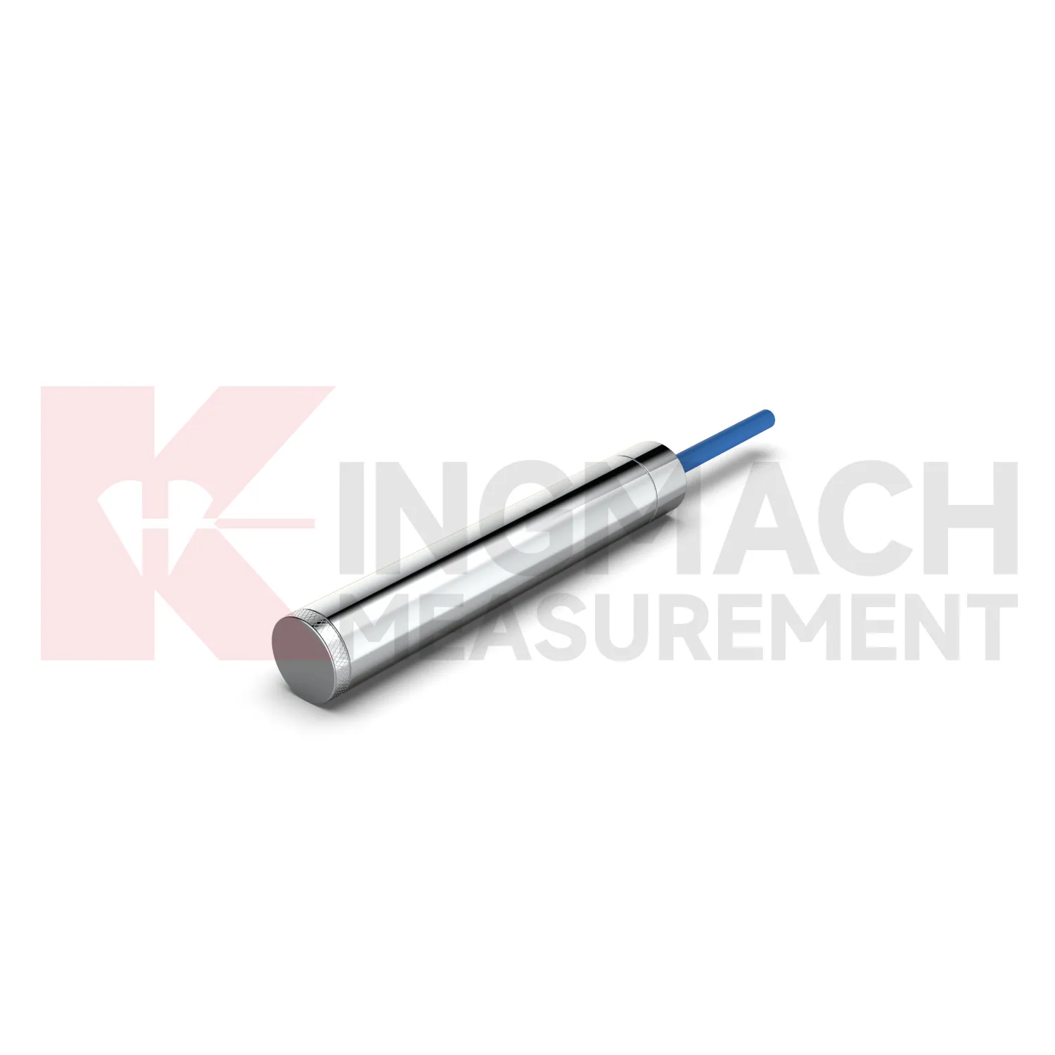
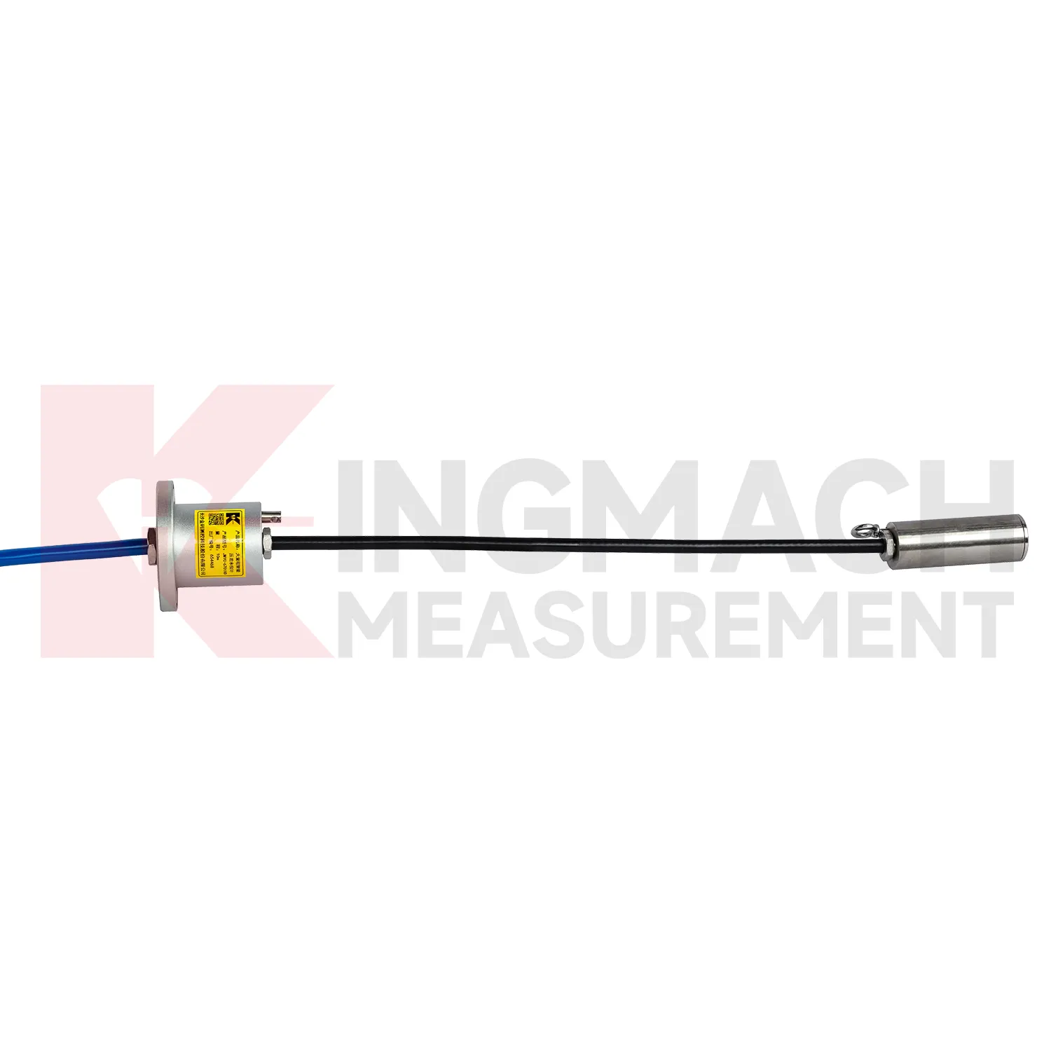
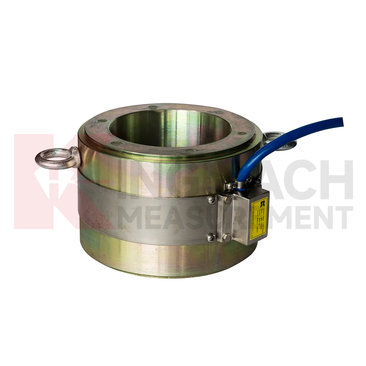
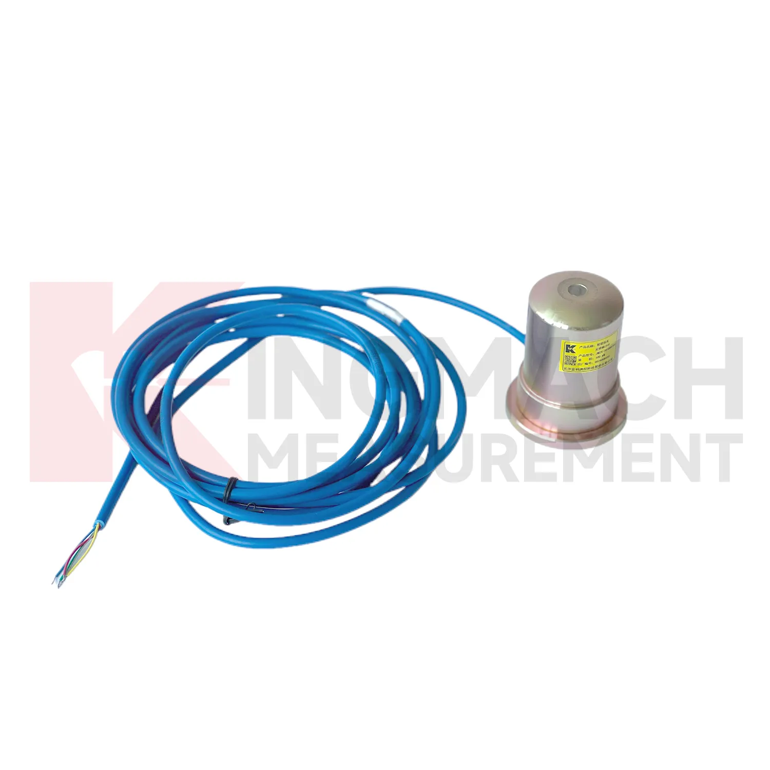
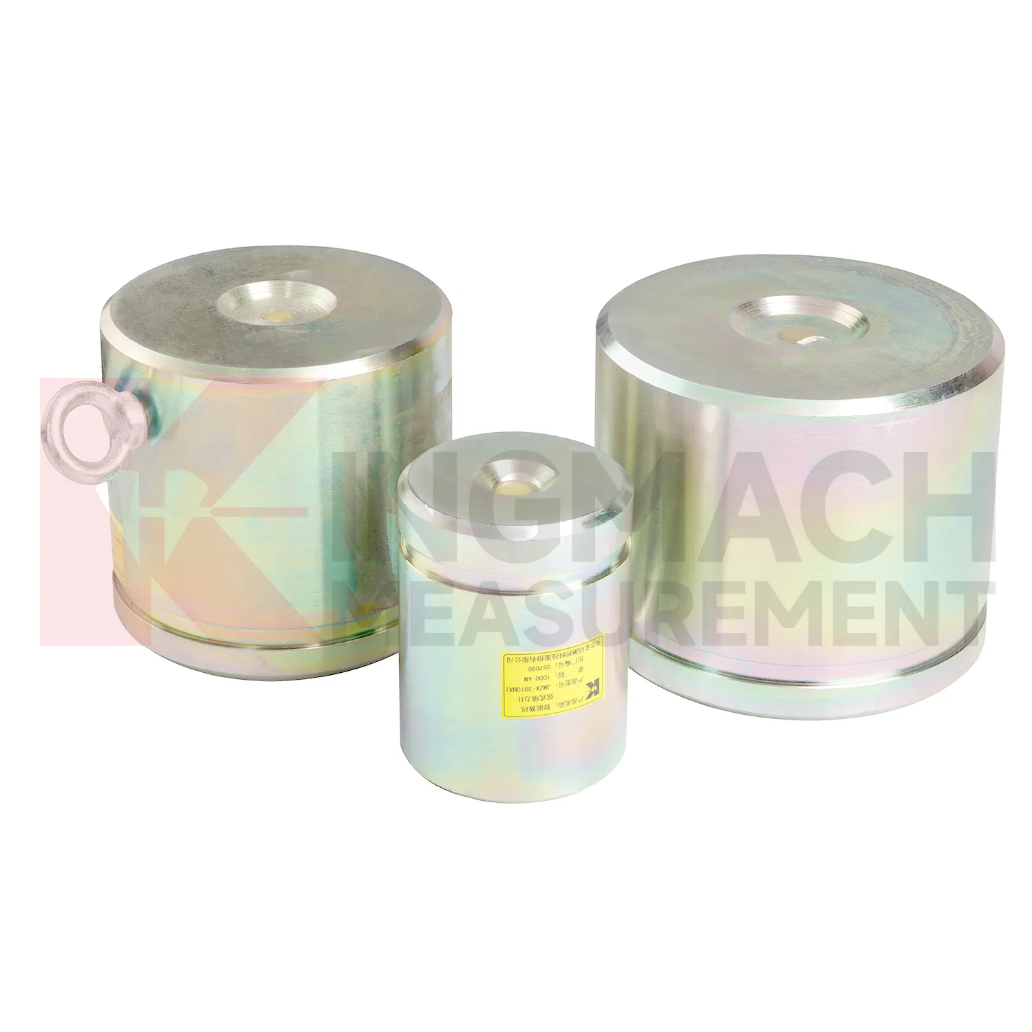
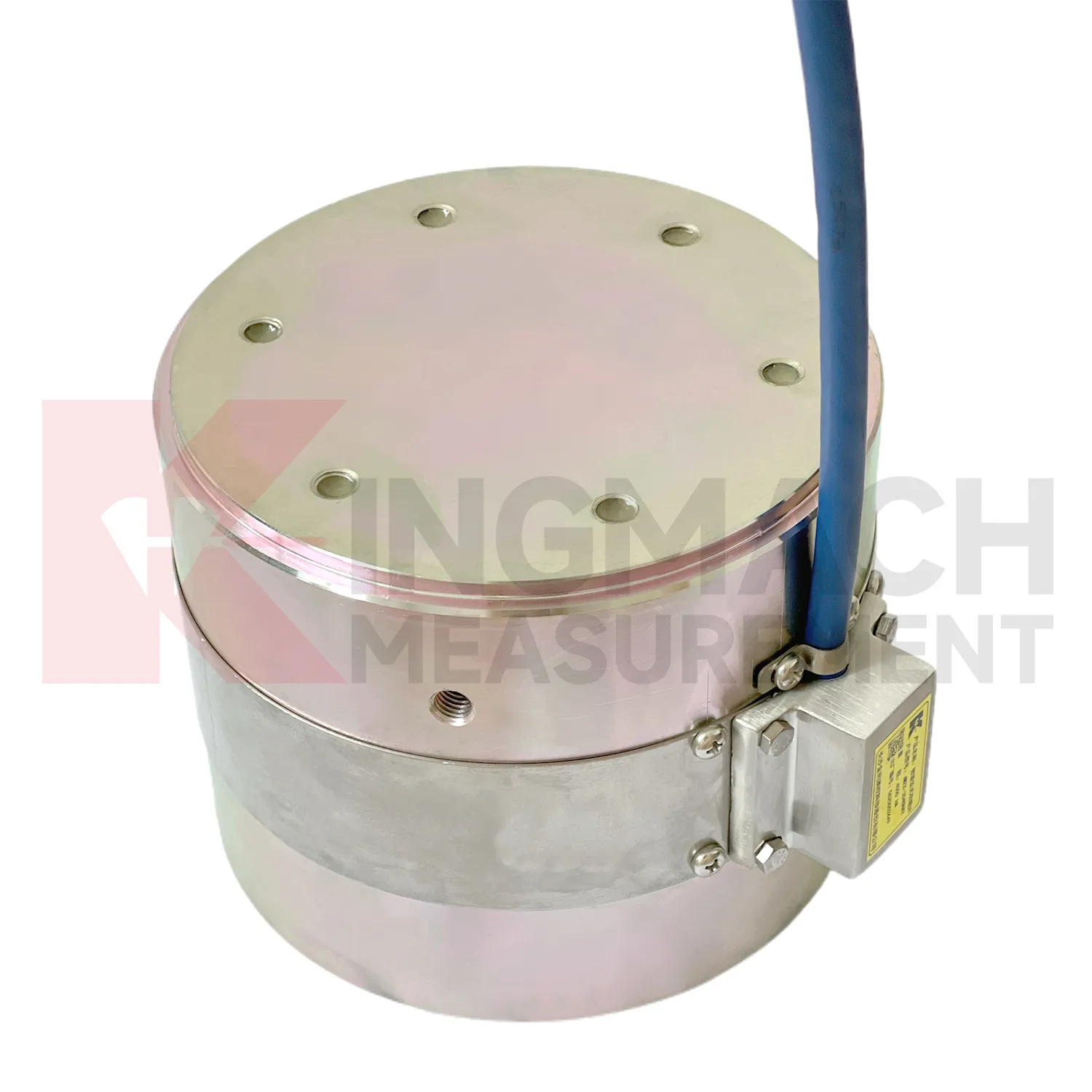
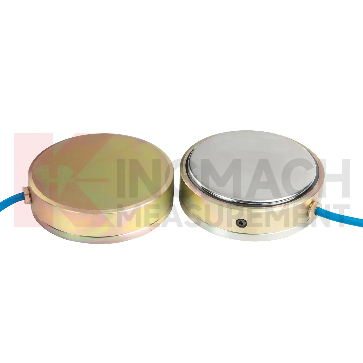
Kingmach wire rope load cell is suitable for projects that need both high capacity and traceable readings. The solid JMZX-35XXHAT line lists a 0.5%FS precision rating, a -30°C to 80°C temperature range, and overload information up to 20 to 50%F.S. for range overload and 300 to 400%F.S. for failure overload. The hollow JMZX-3XXXHAT line lists a 50 year design life, waterproof durability, digital output, and storage for 800 measurement records. The axial force JMZX-38XXHAT line lists 1 MPa waterproofing and direct kN display. Together, these points support force measurement in bridges, buildings, railways, transportation, hydropower, dams, tunnels, and foundation pits. Kingmach also provides monitoring products beyond load measurement, allowing the force record to be compared with movement, pressure, and environmental data. That is useful when a load change needs to be judged against the wider behavior of the structure rather than treated as a disconnected alarm. Kingmach's product pages also refer to industry certifications such as GB/T 13606-2007 and DL/T 269-2022 on selected models. Such references help buyers request documentation that matches project acceptance procedures and owner audit needs. This helps avoid ordering a sensor that is strong enough on paper but difficult to seat, wire, read, or protect in the actual structure.
Application of wire rope load cell
In bridge monitoring, wire rope load cell can be used at cable anchor heads, stay cable force points, pier supports, bearing test positions, and pile load test setups. The pain point is simple: a bridge can redistribute force before visible cracks or displacement appear. Hollow load cells such as the JMZX-3XXXHAT cover 500 kN to 8000 kN and are built around an annular multi-string structure with temperature correction and waterproof durability. Solid load cells reach 10000 kN with 0.5%FS precision, which suits high capacity compression points and bearing capacity checks. During construction, readings can confirm prestressing, lock-off behavior, and support load transfer. During operation, the same point can be reviewed after heavy traffic, temperature swings, maintenance work, or extreme weather. Force data becomes more meaningful when compared with displacement transducers, settlement points, tiltmeters, and visual inspection results. For long span bridges, a load trend that drifts slowly can be more important than a single high reading, because it may reveal relaxation, seating loss, or uneven force sharing. Cable exit direction, waterproof joint location, inspection access, and whether the point will be buried or exposed should be decided before installation. Those details are easy to ignore in drawings, but they often decide whether a field crew can verify the reading later without disturbing the structure.
The future of wire rope load cell
As monitoring standards become more detailed, wire rope load cell will be expected to support both engineering judgment and audit trails. Owners want to know whether a force change is real, when it began, how it compares with design stages, and what action followed. Kingmach load products already include technical features such as 0.5%FS precision on major force models, temperature correction, waterproof construction, direct kN display on axial force meters, and stored measurement records on smart designs. Future systems can tie these details to inspection workflows, maintenance orders, and asset management platforms. That means a load reading will not sit alone in a spreadsheet. It will connect to the sensor model, calibration certificate, installation photo, cable route, alarm history, and nearby movement data. Wireless links and AI screening may speed review, but the foundation remains disciplined measurement. The future belongs to force monitoring records that can be checked, repeated, and understood years after installation.
Care & Maintenance of wire rope load cell
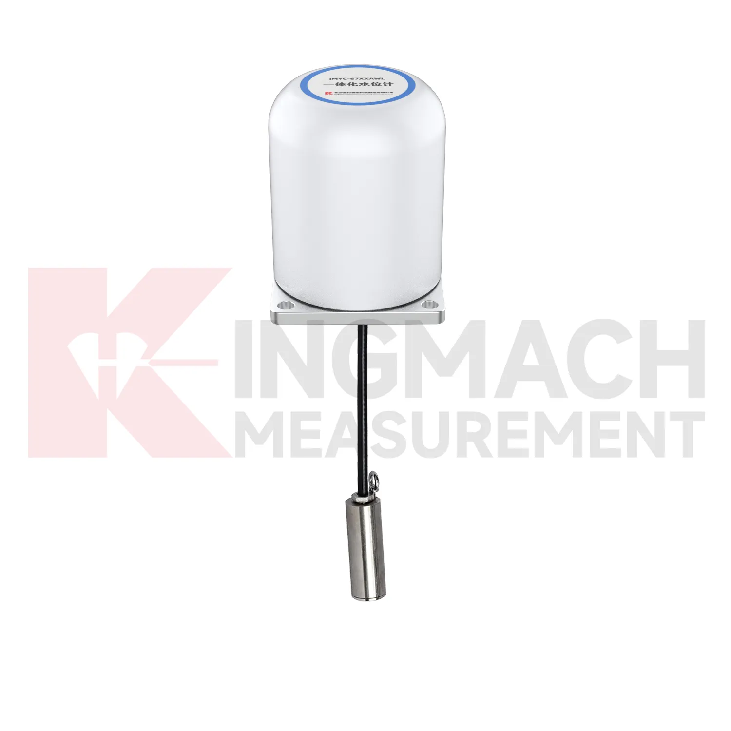
For wire rope load cell working in cold, hot, or wet environments, maintenance should use the product parameters as inspection triggers. Solid load cells list a -30°C to 80°C temperature range, while axial force meters list 1 MPa waterproof performance and earth pressure cells list ±0.5°C temperature accuracy. These ratings help, but field practice still matters. During installation, keep connectors dry, avoid sharp cable bends, prevent direct mechanical blows, and secure the instrument away from water pooling where possible. During long term use, inspect after freeze-thaw cycles, heat waves, storms, flooding, and nearby welding or electrical work. Temperature correction should reduce measurement influence, but readings should still be reviewed with the actual site temperature. If a value moves only during daily temperature swings, check the thermal pattern before issuing a structural warning. If a value changes after water exposure, inspect sealing and cable insulation before resetting alarm thresholds. Do not ignore seasonal effects.
Kingmach wire rope load cell
wire rope load cell often sits between design intent and field behavior. Drawings may state the expected force, but site loading can change when excavation sequence, concrete curing, traffic, reservoir level, grouting, or prestressing work changes. Kingmach supplies sensors and acquisition equipment for bridges, tunnels, dams, subways, slopes, foundations, railways, buildings, and hydropower projects. In these settings, the sensor helps reveal whether a member is carrying its share of the load or taking more than expected. The instrument must fit the force range, the bearing surface, the environmental exposure, and the data workflow. A high capacity sensor with poor installation records is still hard to trust. A moderate range sensor with clear calibration, stable zero, protected cable, and a clean reading plan can produce stronger evidence. For that reason, force monitoring should be planned alongside installation details, not added after the site has already become crowded. This is especially useful when the monitored point becomes hidden after the next work stage.
FAQ
Q: How should wire rope load cell be selected for a bridge cable or anchor point? A: Start with expected force, lock-off load, possible overload, bearing geometry, and access for later inspection. Hollow load cells are commonly used where the anchor or cable passes through the center opening. Q: What range information is available from Kingmach hollow models? A: The JMZX-3XXXHAT series is listed from 500 kN to 8000 kN, with 0.1 kN sensitivity on the 500 kN model and 1 kN on larger listed models. Q: Why does temperature correction matter? A: Cable and anchor readings can move with temperature, so built-in temperature measurement helps reduce false interpretation. Q: Can readings be stored inside the sensor? A: Smart hollow models list storage for 800 measurement records, including time, temperature, zero values, and correction data. Q: What should be checked after installation? A: Check seating, cable protection, connector sealing, zero value, first stable force, and matching channel name.
Reviews
Christopher Martinez
Very satisfied with the readouts & data loggers. User-friendly interface and supports multiple sensor inputs.
Matthew Garcia
Instrumentation cables are durable and perform well even in harsh environments. Will definitely order again.
Latest Inquiries
To protect the privacy of our buyers, only public service email domains like Gmail, Yahoo, and MSN will be displayed. Additionally, only a limited portion of the inquiry content will be shown.
Mia***@gmail.comNetherlands
Dear team, we are interested in your readouts & data loggers compatible with multiple sensors. Do yo...
Emma***@gmail.comCanada
Dear Sir/Madam, we are interested in displacement transducers and settlement sensors for a geotechni...
Related product categories
- load cell zero balance
- load cell connection diagram
- load cell recalibration
- load cell testing
- load cell wiring schematic
- calibration load cells
- calibration of load cell theory
- load cell failure
- load cell technology
- strain gauge load cell wiring
- diagram 4 wire load cell wire connection
- load cell accuracy calculation