
 EN
EN
 ar
ar bg
bg hr
hr cs
cs da
da nl
nl fi
fi fr
fr de
de el
el hi
hi it
it ko
ko no
no pl
pl pt
pt ro
ro ru
ru es
es sv
sv tl
tl iw
iw id
id lv
lv lt
lt sr
sr sk
sk sl
sl uk
uk vi
vi et
et hu
hu th
th tr
tr fa
fa ms
ms hy
hy ka
ka ur
ur bn
bn mn
mn ta
ta kk
kk uz
uz ku
ku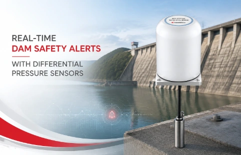
Real-Time Dam Safety Alerts with Differential Pressure Water Level Sensors
Key Takeaways An alert chain needs more than a sensor: define field in...

Load Cell Wiring: Avoid Mistakes & Get Accurate Readings
A loose connection or wrong wire pairing can turn load cell data into guesswork. In geotechnical monitoring, where a few millivolts translate into critical structural insights, reliable load cell wiring isn’t just a detail—it’s the foundation of measurement accuracy. At Kingmach, we’ve learned this through decades of equipping projects worldwide, from deep excavation support to bridge health assessment. This page pulls together practical wiring know-how that ties directly to the sensors we manufacture. Whether you’re integrating a new tension load cell into a monitoring system or troubleshooting an erratic reading on-site, understanding the signal path and noise mitigation is key. We’ll walk through the essentials: excitation voltages, signal conditioning, and the common pitfalls that even experienced techs can overlook. And since no two job sites are identical, we’ll also touch on how a well-thought-out wiring plan fits into a broader measurement strategy—something our engineering team helps customers tailor every day.
Technical Detail
Load cell wiring matters more than most people think. A simple mistake like swapping signal wires or leaving the shield floating can introduce errors that mask real subsurface movement or structural strain. The basic idea is straightforward: the load cell body deforms under force, changes resistance in a strain gauge bridge, and outputs a tiny voltage. But turning that microvolt-level signal into usable data depends on clean, correct wiring. Most Kingmach load cells—think anchor bolt dynamometers, rebar strain meters, earth pressure cells—use a four-arm Wheatstone bridge. Standard output is around 1 to 3 mV/V at rated load. Excitation is typically 5 to 15 V DC, and we supply shielded cables with color-coded leads that match industry conventions. For longer cable runs, six-wire circuits become important; they let the readout sense the actual excitation at the bridge and compensate for voltage drop. We ship many products with six-conductor cable on request. Shielding and grounding also demand attention. The braided shield inside the cable needs to connect only at the instrument end—otherwise you risk ground loops. Our datasheets and wiring diagrams spell out pinouts, color codes, and recommended connections for each sensor type. Because Kingmach manufactures in-house and stocks a wide range of geotechnical instruments, we can offer custom cable lengths, connector types, and even pre-wired junction boxes that speed up field installation. Our technical support team handles wiring-related questions every day, whether it’s a noise problem from a pump nearby or a zero-shift after a lightning storm. Beyond the cable, the bigger picture includes data loggers, wireless nodes, and cloud dashboards—all parts that we help integrate. If your project demands a non-standard output like 4-20 mA or RS485 digital, we build that in at the factory. With distribution in over 30 countries, getting a properly wired system to your site is a question of logistics, not luck. Reach out with your wiring scenario; we’ll propose a setup that starts with a clean signal and ends with reliable data.
News
Key Takeaways An alert chain needs more than a sensor: define field in...
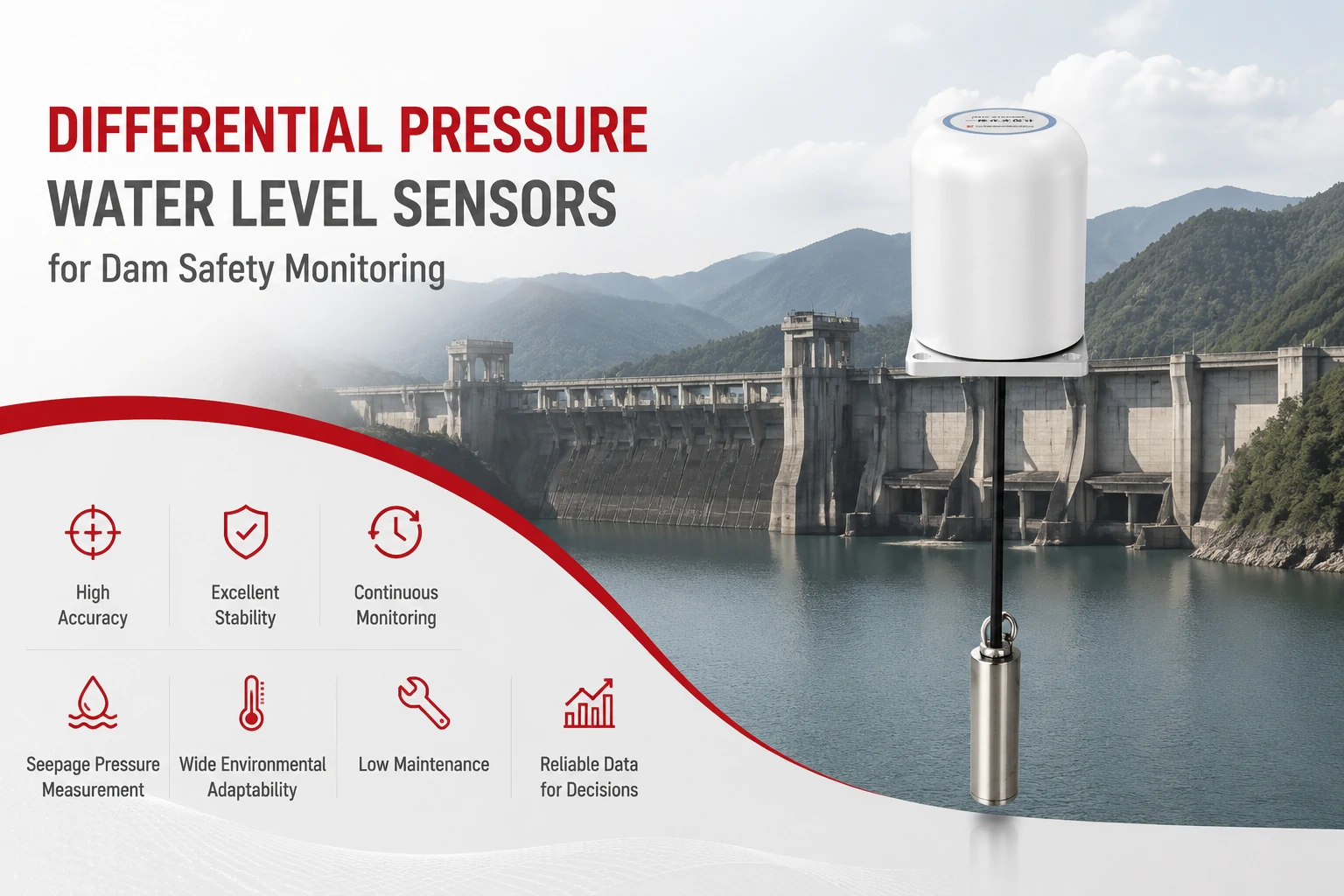
Key Takeaways The strongest fit is usually a confined, submerged, or s...
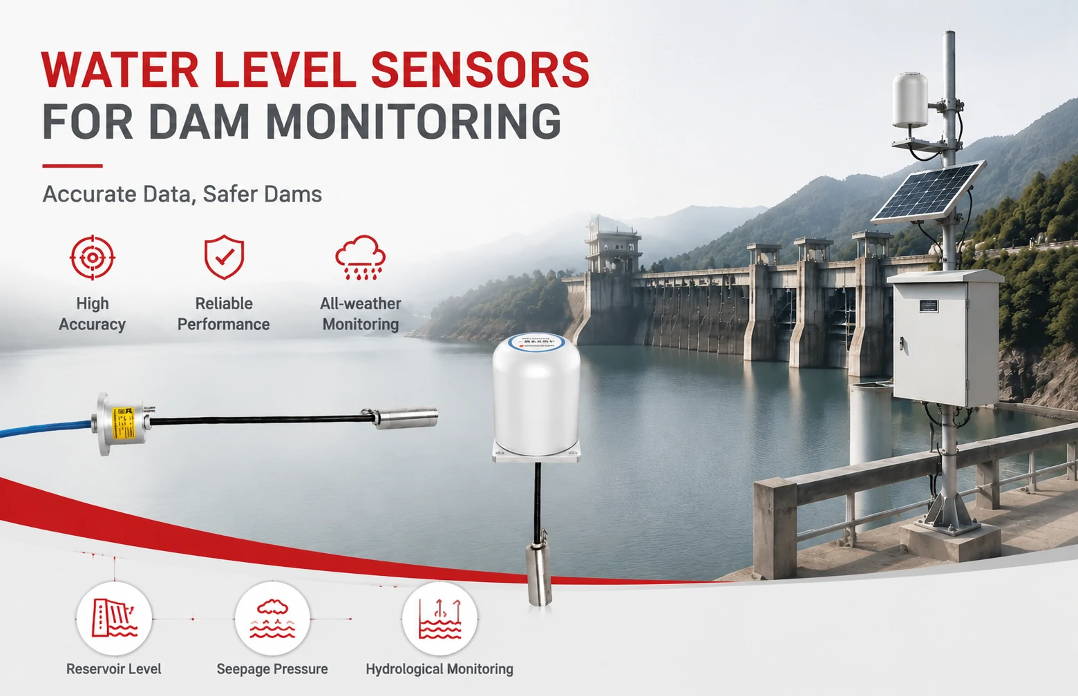
Kingmach Water Level Sensors for Dam Monitoring: A Buyer's Guide to Differential Pre...
Products
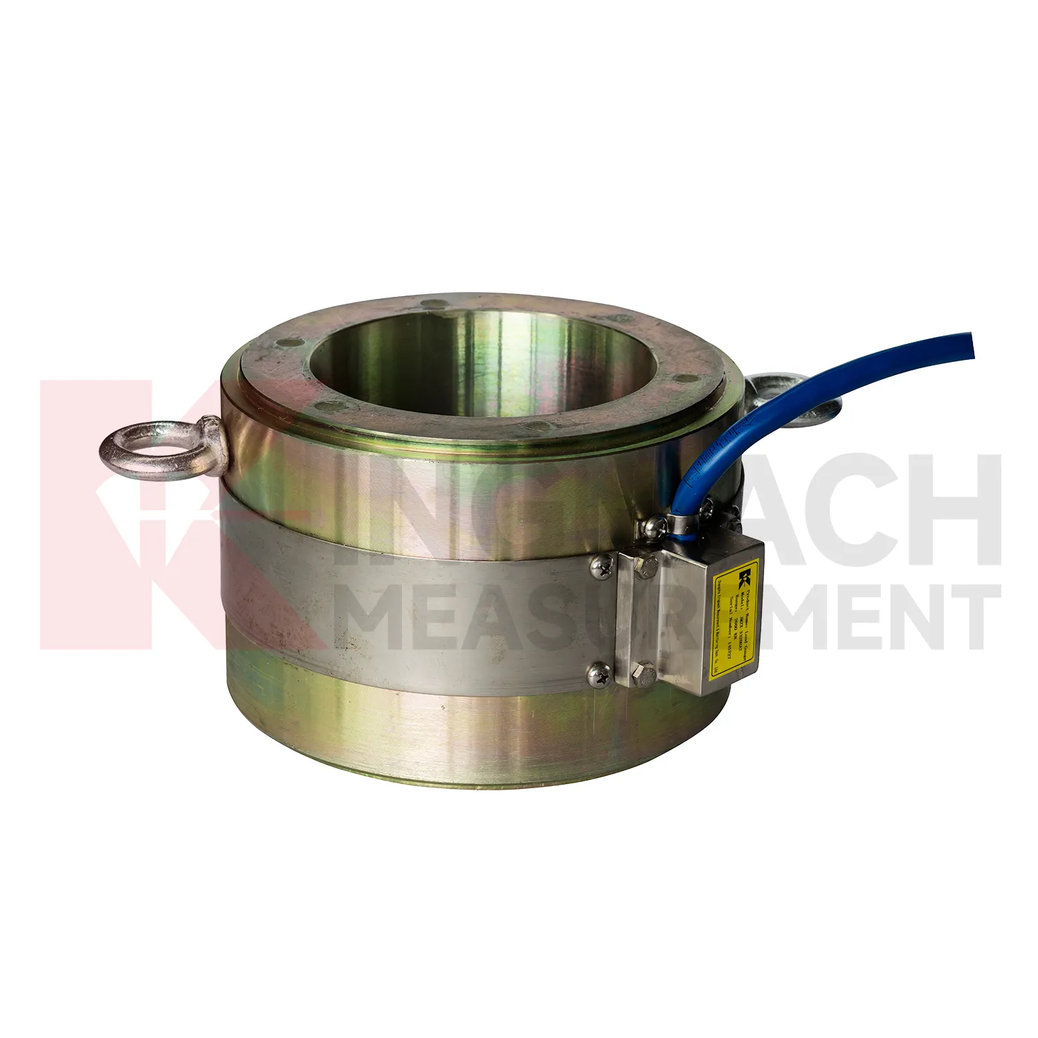
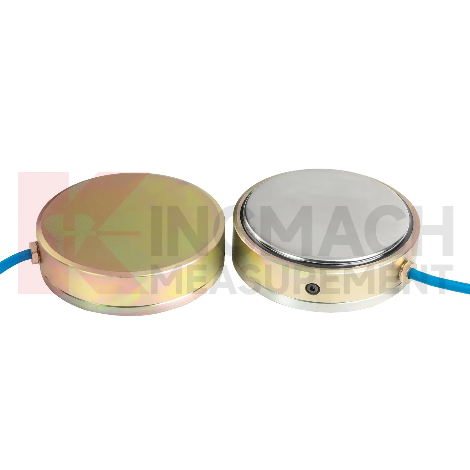
Large Earth Pressure Cell ( VW & Smart Type) JMZX-51XXAT/ ATM
View Details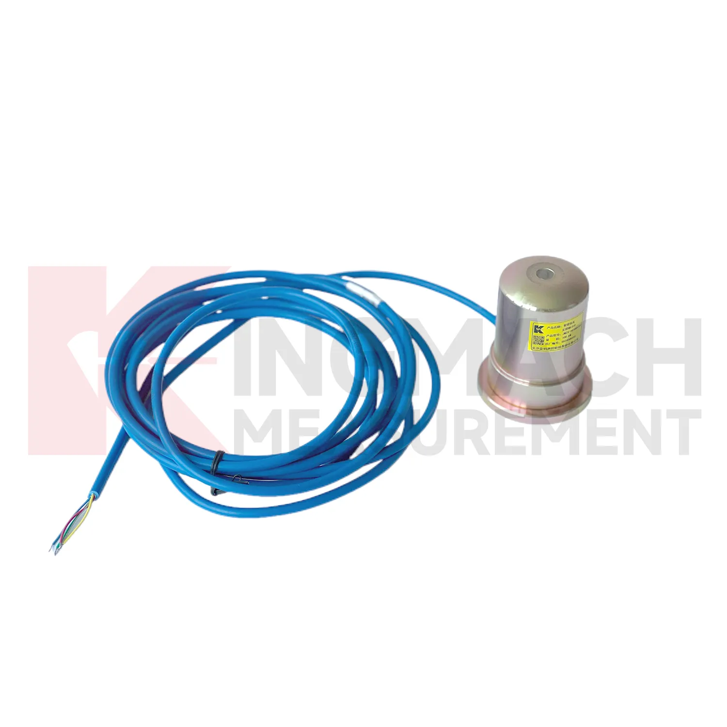
Smart Formwork Axial Force Meter(VW)JMZX-39XXHAT
View DetailsFAQ
A 4-wire circuit carries excitation voltage to the bridge and brings back the signal, but it can’t compensate for resistance in the cable itself. On long runs that resistance drops a bit of the excitation, shifting the sensitivity. A 6-wire cable adds two sense wires that measure the voltage right at the load cell. The readout then adjusts the supply to keep the excitation stable, so you get more accurate readings regardless of cable length or temperature swings. For most geotechnical installations with cables over 30 meters, we recommend six-wire connections.
Noise often sneaks in from variable-frequency drives, radios, or nearby power lines. The built-in braided shield inside Kingmach cables does most of the work if you handle it properly. Connect the shield to the data logger’s ground terminal at one end only—usually the instrument end—and leave the other end floating. Avoid routing signal cables in the same conduit as AC power. If noise persists, a ferrite bead clamped around the cable near the logger can help. For extreme cases, we can supply sensors with additional internal filtering.
Yes, cables can be extended, but it changes the bridge resistance and sensitivity slightly. For a simple splice, use a shielded junction box and solder connections to keep signal integrity. Then recalibrate the system as a whole—hang known weights or apply a reference force at the sensor to check the output. Kingmach often provides factory-fitted longer cables or field connectors that don’t require recalibration, since we match the impedance during production. If you’re unsure, send us the cable specs and we’ll calculate the expected shift.
Drift can come from moisture in connectors, a compromised shield, or even a damaged strain gauge. First, inspect all wiring junctions for corrosion or loose crimps. Measure the excitation voltage at the load cell end: if it’s unstable, check the power supply and cable continuity. For our sensors, typical zero drift is below 0.1% FS per year under normal field conditions, so a sudden drift usually points to a physical fault in the wiring or water ingress. We have a troubleshooting guide that steps through insulation resistance checks and signal isolation tests.
Every sensor we ship includes a printed wiring sheet with color codes and pinouts, and you can download the latest versions from our website. For custom configurations—like dual-bridge setups, built-in amplifiers, or mixed RS485/analog output—our engineers prepare a project-specific wiring document. Just tell us the sensor model and the readout equipment you’re using, and we’ll send a connection drawing. If field support is needed, our regional distributors often have experienced techs who can visit your site and verify the setup.
Share your product type, target capacity, and application requirements. Our team can review the details and recommend a practical next step.
If you are interested in our products or want to become our partner.
Please leave your contact information, our team will contact you as soon as possible.
Mail: [email protected]
Contact Us: +8613808434127
Address: No. 188 Tongzipo West Rd, Changsha, Hunan, China